
 > 제품소개 >
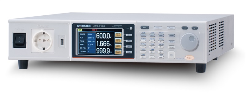


Programmable AC Power Source APS-7000 Series
- 모델명:
- APS-7100 / APS-7050
- 특징:
- ▶ 채널수 : 1채널
▶ 전압 범위 : 0~155Vrms, 0~310Vrms
▶ 전류 범위 : 4.2A/2.1A (APS-7050), 8.4A/4.2A (APS-7100)
▶ 최대 출력 전력 : 500VA, 1kVA
상세설명
APS-7000 is a series of programmable linear AC power supply, with the height
of 2U and output frequency range is 45~500Hz, , the maximum rated output for
APS-7050 is 500VA, 310Vrms, 4.2Arms and APS-7100 is 1000VA, 310Vrms, 8.4Arms.
The optional collocation can be extended to the maximum output voltage of
600Vrms and maximum output frequency of 999.9Hz. The APS-7000 series comprises
nine measurement and test functions (Vrms, Irms, F, Ipk, W, VA, PF, Ipk hold,
CF), and provides user interface similar to that of AC Power Meter. The APS-7000
series, via switching many sets of current levels to increase small current
measurement resolution, is ideal for the LED industry and standby mode power
consumption test. To meet the test criteria of line voltage fluctuation often
seen in consumer electronics, APS-7000 series not only supply a stable source of
AC, they also features five methods to cope with special purpose or abnormal
voltage, frequency, and phase; ten sets of the Simulate mode simulate power
outage, voltage increase, and voltage drop; ten sets of the Sequence mode allow
users to define parameters and produce sine wave by editing steps; ten sets of
the Program mode can edit AC waveform output and define the ceiling and floor
level of measurement items for different DUT; Ramp Control allows users to set
the variation speed for output voltage rise and fall; Surge/Dip Control
simulates DUT’s input power producing a Surge or Dip voltage overlapping with
output voltage waveform at a specific time.The series is ideal for user to
produce high complicated waveform and transient waveform to verify electronic
product operation under adverse condition.APS-7000 series currently involves
APS-7050 & APS-7100 as below:
Model Name
Max. Output Current
Power Rating
Output Voltage
APS-7050
4.2A/2.1A
500VA
0~310.0Vrms
APS-7100
8.4A/4.2A
1000VA
0~310.0Vrms
APS-7050 Output Operation Area
APS-7100 Output Operation Area
Sequence Mode
There are ten sets of Sequence mode and each set has 0~255 steps.
The time setting range for each step is 0.01 ~ 99.99 seconds. Combining many
sets of steps to edit required waveforms satisfies users’ requirement of highly
complicated waveforms.
Simulate Mode
This mode can rapidly produce different simulated input transient waveforms
such as power outage; voltage rise and voltage fall etc. for engineers to
evaluate the impact on DUT posed by the transient phenomena. For instance,
capacitor endurance test.
Power Outage
Voltage Rise
Voltage Fall
Program Mode
This mode allows users to set ceiling and floor specifications to produce
PASS/FAIL result after the measurement is done. It can also show test results
for each test procedure or only show the last result. There are ten sets of
Program mode and each set has 50 sets of memories. Each memory comprises 9
steps. Each Program will perform according to memories sequence, self-defined
loops or designated steps to stop.
Program Mode
ARB Mode
This mode provides more than 50 different waveforms in 7 major categories to
rapidly simulate distorted AC voltage waveforms.
Sine waveform : Standard AC Waveform
Triangle waveform : Power harmonic output simulation is triangle
waveform
Staircase waveform : Simulate square waveform and staircase
waveform for commercial UPS
Clipped sinewave : Simulate grid power supply heavy load
waveform
Crest factor waveform : Simulate rectified filter current
waveform by capacitor input
Surge waveform : Simulate grid power supply’s peak
over-voltage
Fourier series synthesized waveform
Simulate real output power waveform. Distorted power waveform is
produced due to output impedance and non-linear effect such as inductance,
capacitance, and parasitic capacitance effect. For example: motor.
Ramp Control
Ramp control allows users to set output voltage rise or fall speed which is
based on time (1ms) or voltage (1Vrms) unit.
Tup-> 0.1 ~ 999.9msTdn-> 0.1 ~ 999.9ms
Vup-> 0.01 ~ 99.99 VrmsVdn-> 0.01 ~ 99.99
Vrms
Mode=Time, Tup=1 msec, VAC=100V, Freq=50Hz, Ramp
output=on.
Mode=Voltage, Vdn=2Vrms, VAC=100V, Freq=50Hz, Ramp
output=off.
Surge/Dip
Control
Overlapping a Surge/Dip voltage on a normal voltage as the input power for
DUT allows users to simulate Surge/Dip situation and evaluate DUT
characteristics.
Dip
Surge
T Ipeak, hold
function
T, Ipk Hold sets delay time (1ms~60 seconds) for measurement after the output
of Ipeak value and the maximum value will be retrieved. Update will be preceded
only if measured value is greater than the original value. Ipk Hold is for
measuring transient inrush current as soon as the equipment power is on that is
usually done by oscilloscope and current probe. T, Ipk Hold delay time setting
can be applied to measure inrush current of sequentially activated DUT.
Ipeak Measurement
Control Panel
Characteristics
There are two control panel modes: Standard mode and Simple mode. Both modes
are shown as below. Standard mode combines settings and AC Power Meter
measurement window display. Users apply Function key (F1~F3) to select required
measurement items. There are nine items for selection. Simple mode shows all
measurement items on the display.
Standard Mode
Simple Mode